
Data Logger software user guide onlineview
- Index
- Brief Introduction
- Software Startup
- Registration method
- Main function of Data Logger software
- Point Select
- Data Record
- Data Record Done
- Parameter Set
- Real time Trend
- Manual Mode
- Exit
Vibroflotation with pressure water and air Data Logger software User’s Guide
Brief Introduction
Data Logger software must work with the matching equipments .The system structure as follow(Figure 1):
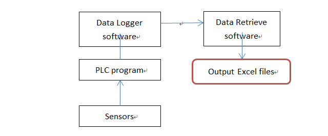
Figure1
Software Startup:
The Data Logger software will start up automatically after the boot of the industrial tablet PC. There is an initialization process before showing the main interface. The prompt message are shown as figure 2:
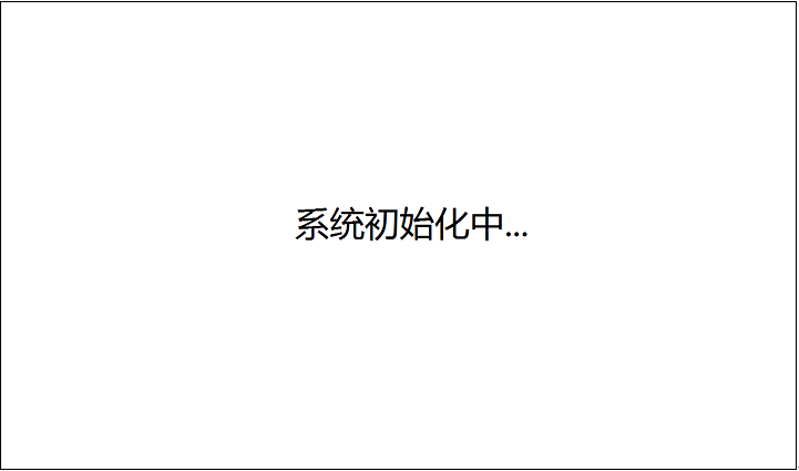
Figure2
If the Data Logger software is not registered or the license file is missing, a popup window of registration displays as figure 3. And the Data Logger software will exit automatically after 30 seconds, as figure 4 shows.
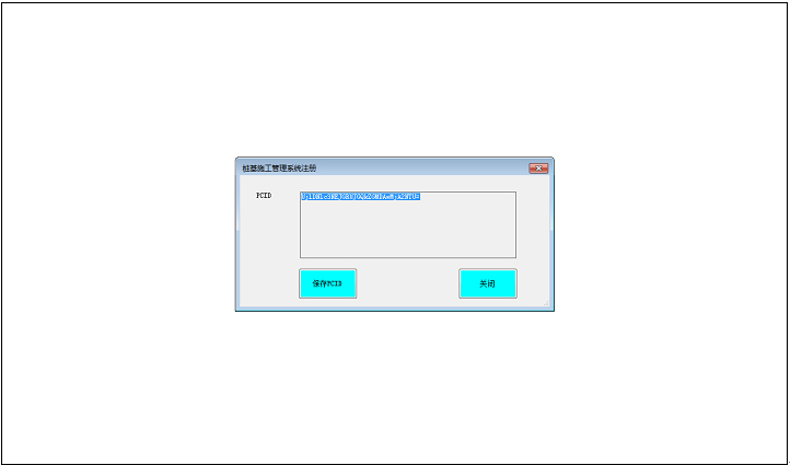
Figure3
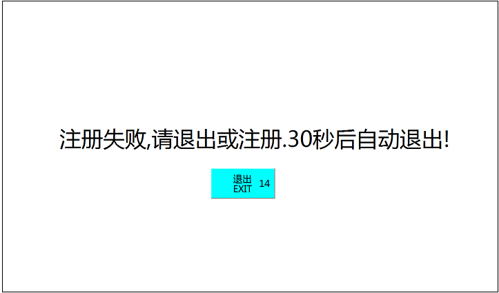
Figure4
(Data Logger software registration method: In figure2,Press the button named “保存PCID”, a new file named as “machine.lic” will generated under the folder of “D:\elant”(this folder will generate automatically).Send a copy of this file to Chengdu ELANTTECH Co.; Ltd for the license file. A license file named “elantsn.lic” will be returned from Chengdu ELANTTECH Co.; Ltd. Please copy the license file to the folder of “D:\elant” and the registration will done.)
Main function of Data Logger software
Point Select
The main interface of Data Logger software is shown as figure 5:
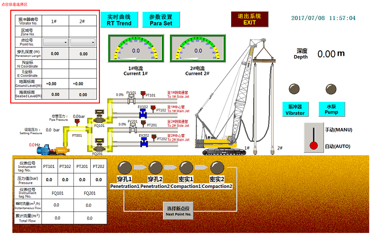
Figure5
In figure 5, the top left corner with red frame is the zone of Point information. You can select “Point No.” by using list-box, and then, the matching properties will display(such as: ”Zone No.” , ”Penetration Length” , “N Coordinate” , “E Coordinate” , “Ground Level” , “Seabed Level”) automatically(as figure 6 shows).
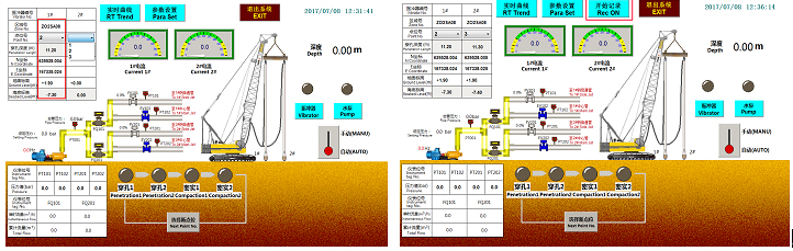
Figure6 Figure7
The “Rec ON” button will not be shown unless both Point No. have been selected. The “Rec ON” button located at the central top of the main interface(the button with red frame in figure 7)
If you see a prompt message is displayed as figure 8 shows after you click the “Rec ON” button, it means there is an error occurred. In this situation, it means you should select both “Point No.” and record action will not be triggered.
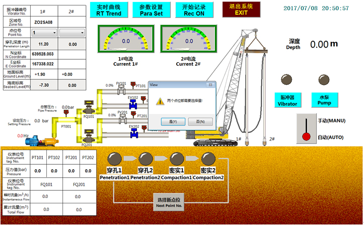
Figure8
A prompt message will also be displayed if you select the same value for both “Point No.”, as figure 9 shows, and the “Rec On” button will not be displayed.

Figure9
If you select “Point No.” of “Vibrator No. 2#” first, a prompt message will also be displayed. In this situation, it means you should select “Point No.” of “Vibrator No. 1# “first(As figure 10 shows)
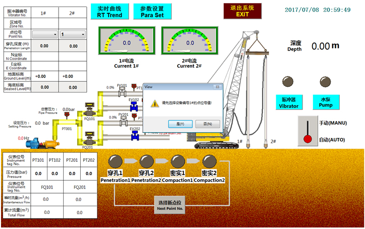
Figure10
If the point that you select has been recorded before, a prompt message will be displayed to remind you and you can have two options(as figure 11 shows):
Option 1: If you choose “YES” then the history data of the point will be covered after your click “Rec On” button.
Option 2: If you choose “NO” then you have to select another value for the point.
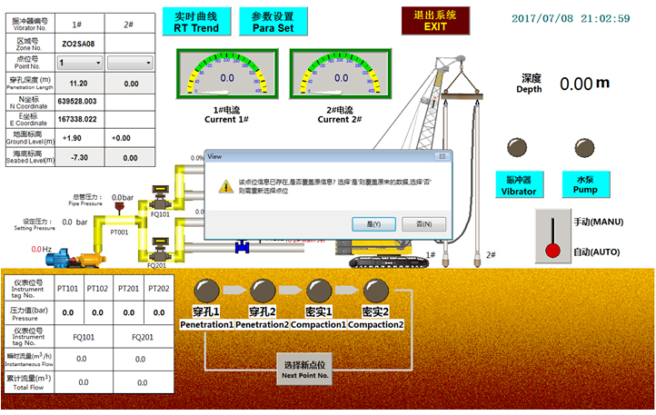
Figure11
Data Record
If both “Point No.” have been selected correctly, the “Rec ON” button will be displayed in the main interface (as figure 12 shows). Click this button and a data recording process will be triggered. The data , upload by PLC, will record to a database. During the process of recording, “Rec ON” button will be hidden in case of clicking incorrectly.
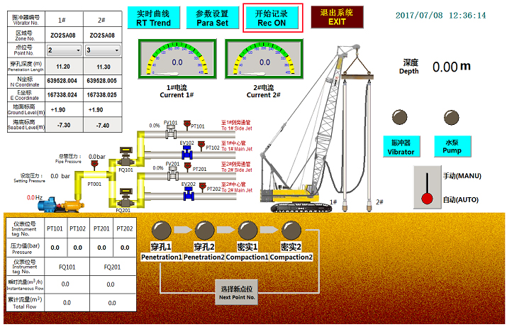
Figure12
After recording, a popup window of new point selection will be displayed.(as figure 15 shows) Input correct value for both vibrator and press “Confirm” button, a data recording process will be trigged automatically, too.
The following shows how to input new point:
The left textbox stands for point of vibrator No.1 and the right textbox stands for point of vibrator No.2. Please enter a value of the left textbox first and then press the “Match” button beneath. If match successfully, a word “Match” in red color will show at the right side of the button. If not match, a prompt (“No Match Point” in red color) will show at the right side of the textbox. After vibrator No.1 is matched, you can then enter a value of the right textbox and press the “Match” button beneath, too. When both vibrator are matched, a “Confirm” button will show. Press the “Confirm” button will start a new data recording process.(no match shows in figure 13, match shows in figure 14)
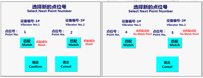
Figure13 Figure14
Data Record Done
During data recording, data records every 1 second. When the whole process of vibrator is finished, data recording will stop automatically and a popup window will display to input new point number.(as figure 15 shows) If there is no more point, you can press “Cancel” to exit.
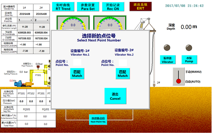
Figure15
Parameter set
Press “Para Set” button in the main interface, you can switch to parameter set interface. In order to avoid unauthorized entrance, you should input password before parameter set interface shows. The password input interface shows as figure 16. The password consists of 4 numbers.
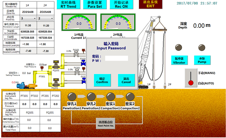
Figure16
The parameter set interface shows as figure 17. All the data you input will be saved in PLC permanently, so you don’t have to re-input.
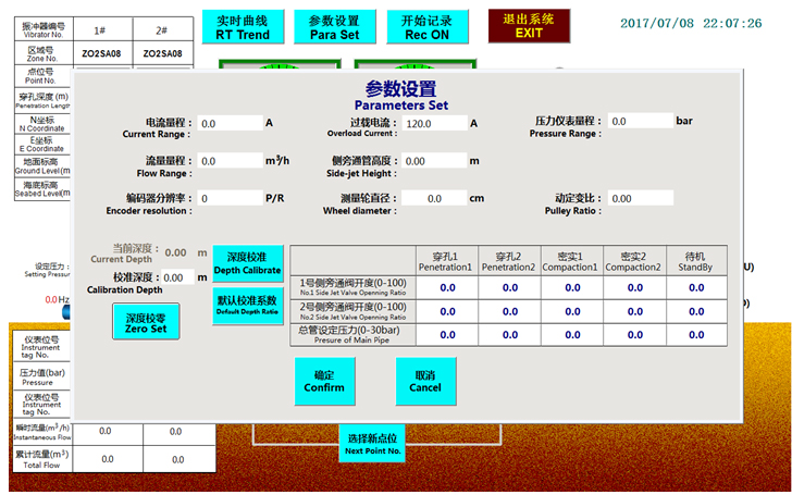
Figure17
Real time Trend
Real time trend of depth and currents will display if press the “RT Trend” button in the main interface and the time span is 10 minutes. The default real time trend is depth.(as figure 18 shows) Different real time trend can be switched by click the buttons on the top. The other two real time trend is “RT Trend of Current1”(as figure 19 shows) and “RT Trend of Current2”(as figure 20 shows). Press “Return” button will go back to the main interface.
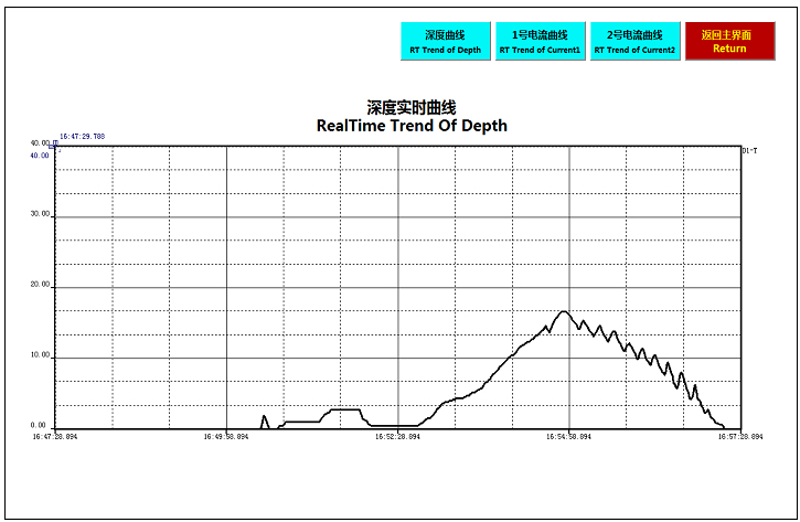
Figure18
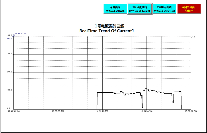
Figure19
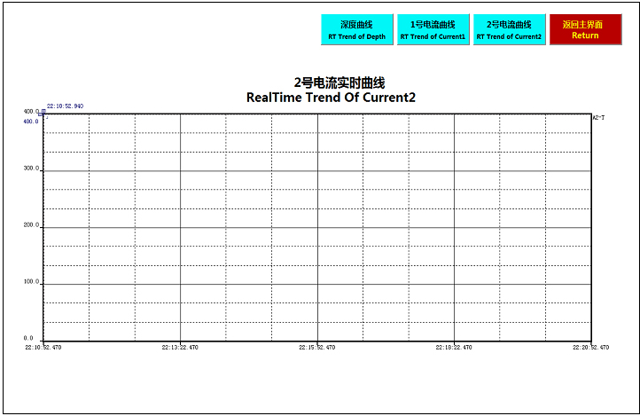
Figure20
Manual Mode
Press AUTO/MANU switch button in the main interface(the part with red frame in figure 21)will switch to manual mode.。Under this mode, different stage of vibroflotation can be set manual by press corresponding button and two valves can be opened or closed manual by press corresponding button, too.
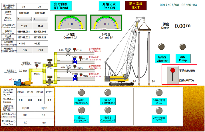
Figure21
Exit
Press “EXIT” button in the main interface will show a exit window.(as figure 22 shows)Press “Confirm” if you want to exit or press “Cancel” if not.
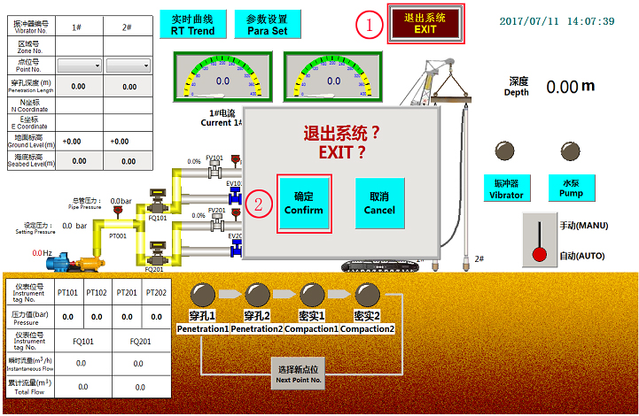
Figure22
- © 2011 Chengdu Elanttech Co.; Ltd. |
- 蜀ICP备15011641号-1